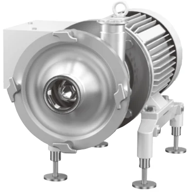
Máy bơm ly tâm thực phẩm inox vi sinh
Hygienic, Sanitary, AsepticCentrifugalPumps
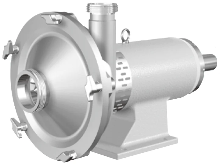
Equipped with TopRunner motor
High efficiency Performance | Pumps equipped with top runner motor | ||||||
INDEX |
| ||||||
Type symbol | Material symbol | Details | Motor capacity | Page | |||
EZN | 316 | Direct connection; floor-mounted; side terminal box | 0.75~3.7 kW | 4 | |||
304 | |||||||
EZM | 316 | Direct connection; floor-mounted; side terminal box | 0.75~15 kW | 4 | |||
304 | |||||||
EZL | 316 | Direct connection; floor-mounted; side terminal box | 1.5~15 kW | 4 | |||
304 | |||||||
EZB | 316 | Direct connection; floor-mounted; side terminal box | 5.5~15 kW | 4 | |||
ESM | 316 | Separate; fixed to floor | 22 kW | 5 | |||
304 | |||||||
ESL | 316 | Separate; fixed to floor | 22~30 kW | 5 | |||
304 | |||||||
ESB | 316 | Separate; fixed to floor | 22~37 kW | 5 | |||
EZH | 316 | Small-capacity closed impeller | 1.5~15 kW | 4, 5 | |||
ECN | 316 | Coupling; floor-mounted; explosion-proof motor | 1.5~3.7 kW | 7 | |||
304 | |||||||
ECM | 316 | Coupling; floor-mounted; explosion-proof motor | 1.5~7.5 kW | 7 | |||
304 | |||||||
ECL | 316 | Coupling; floor-mounted; explosion-proof motor | 1.5~7.5 kW | 7 | |||
304 | |||||||
ECB | 316 | Coupling; floor-mounted; explosion-proof motor | 5.5~7.5 kW | 7 | |||
ECH | 316 | Coupling; floor-mounted; explosion-proof motor | 1.5~7.5 kW | 7 | |||
Material | |||||||
SUS316 (or equivalent) SUS304 (or equivalent) |
|
| |||||
Production standard | |||||||
External finish | Beads shot blast | ||||||
Internal finish | #320 to #400 Buff polishing | ||||||
In-between surface tolerance | ±1.5mm or less | ||||||
Parallelism at ends | ±0.5° | ||||||
Squareness | ±0.5° | ||||||
Lubricant application specifications | |||||||
Application specifications | Application area | Note | |||||
Standard specifications | Shaft axial part | - | |||||
Wetted surface lubrication prohibited area | Shaft axial part (Partial wiping with alcohol) | Be sure to give lubricity to the sliding seal part with fresh water, etc. before starting operation.
| |||||
Lubricant | NOK Kluber PAPALIQ GTE 703*1 (NFF category H1) | ||||||
| * 1 Conforming to the Food Sanitation Law | ||||||
► Pump selection and ordering | |||||||
When using our pumps, be sure to use them within the respective pump specifications. If pumps will be use outside the scope of specifications, a design with higher safety taking into consideration various conditions is required. We would be pleased to offer consultation if you provide us with information. | |||||||
► Ordering | |||||||
O Refer to the specifications on page 13 and the type symbol table on page 14 to specify your required pumps. | |||||||
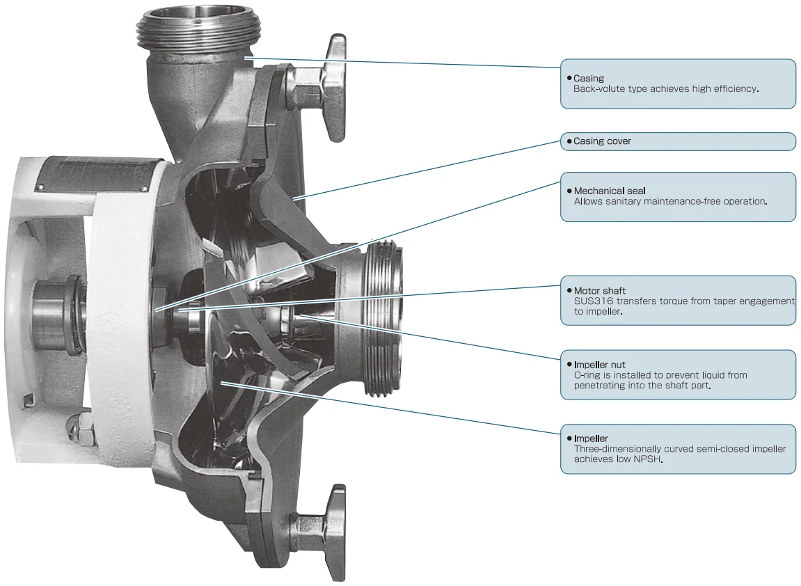
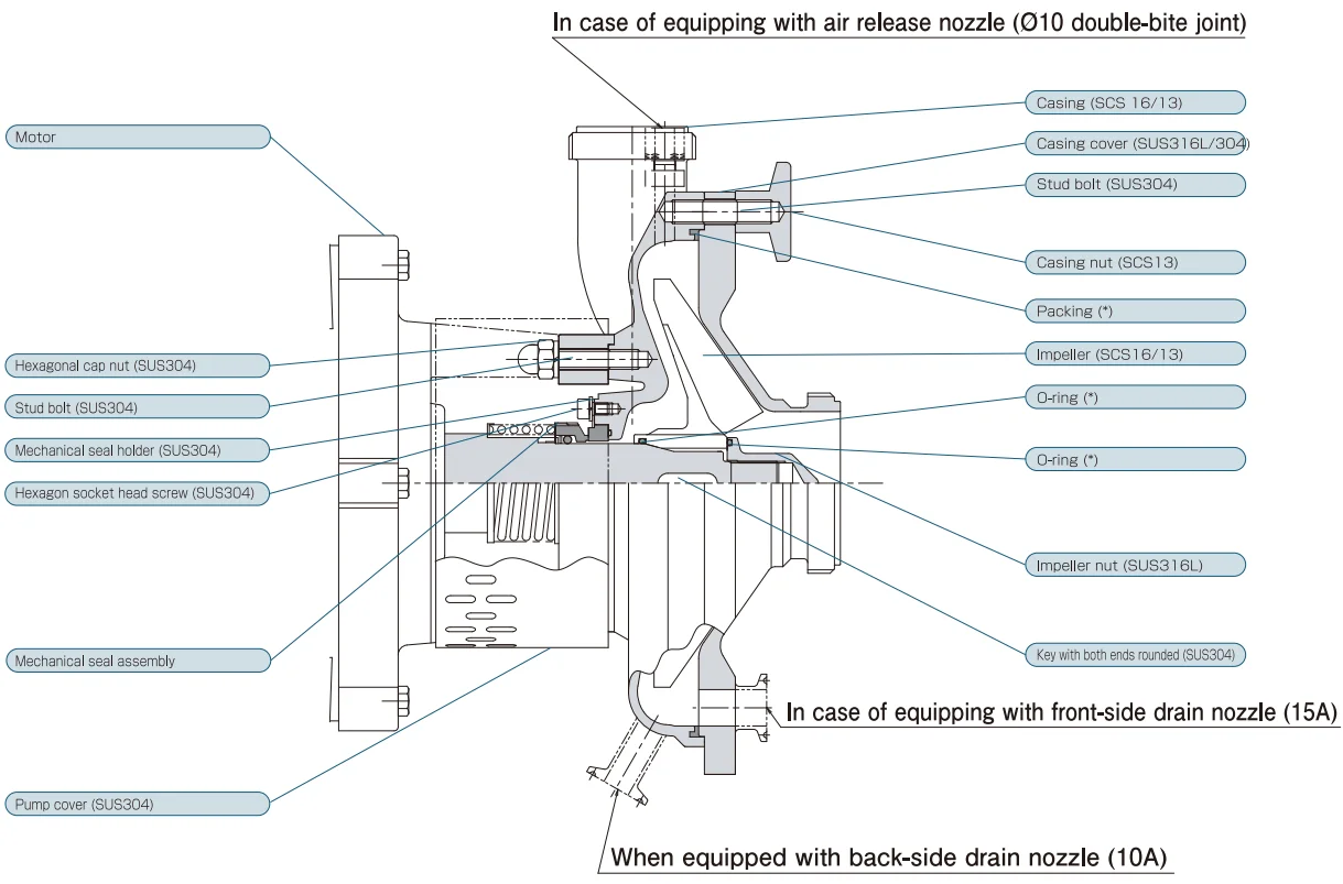
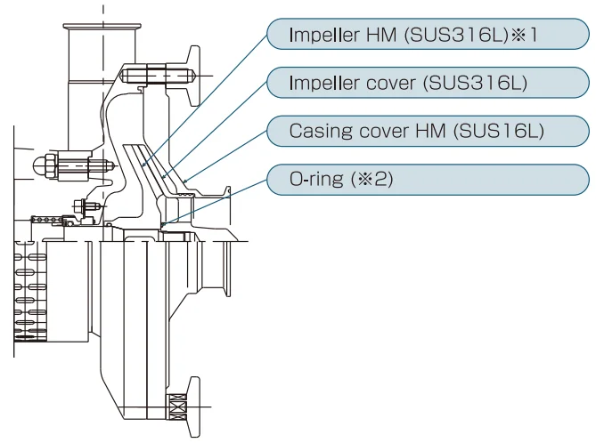
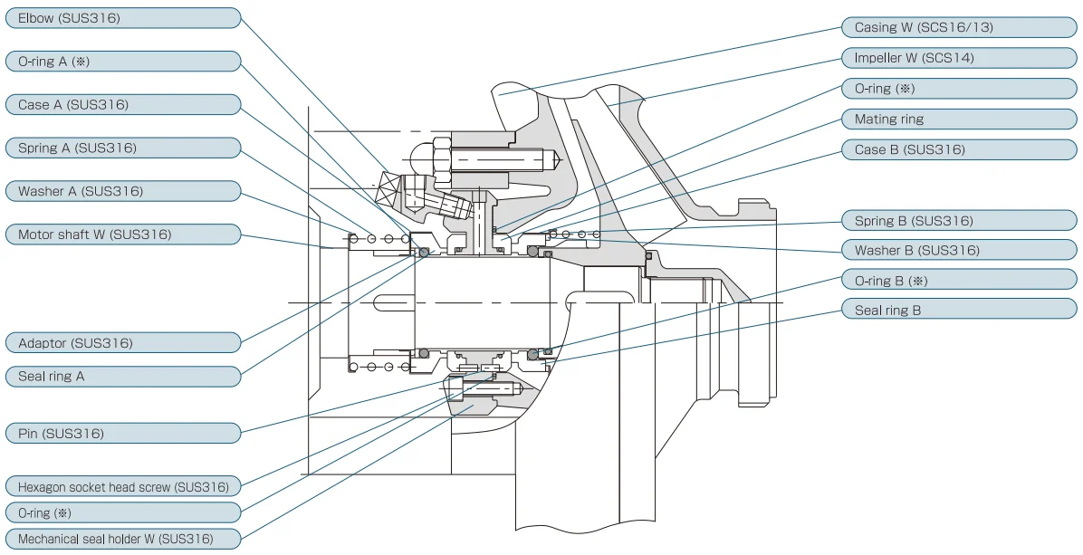
► Cross-section view |
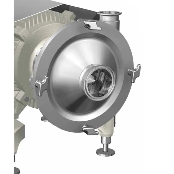
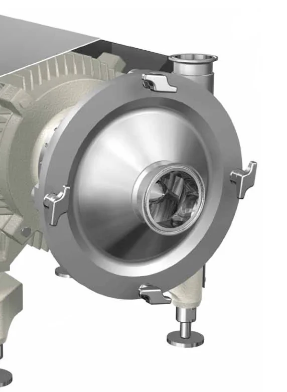
● Achieves high efficiency using a three-dimensionally curved semi-closed impeller and a back-volure type casing. (Pump efficiency np = 70%) ● Achieves low NPSH using a original intake angle and an appropriate impeller profile. (3m at NPSH (RH) 60m3) ● Achieves low-noise operation using a special motor and a original motor cover. (Noise reduced by 3 to 10 dB in comparison with our conventional model) ● Realizes a rigid structure through development of a top runner motor specifically for pump use. (Larger load-side bearing, shaft seals with outdoor specifications, etc.) ● Achieves high hygienic property by using a reversible clutch-type external mechanical seal. ● Main body lineup of five types (N, M, L, B and H) which can cope with any capacity and pump head. (Capacity: Up to 150 m3/hr; Pump head; Up to 100m; Motor power: 0.75 to 37kw) ● Small-capacity closed-impeller type (EZH) achieves high-efficiency operation at low noise and low NPSH. |
|
► Cross-section view (EZ, ES type) |
|
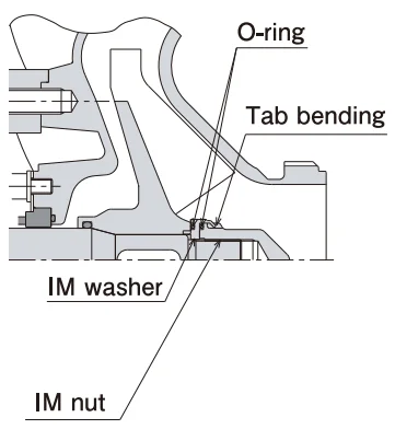
Impeller nut compatible with back wash (reverse) |
 |
* Refer to "(1) Material classification" on Page 14 |
* Conforming to food hygiene test (Ministry of Health and Welfare builletin). |
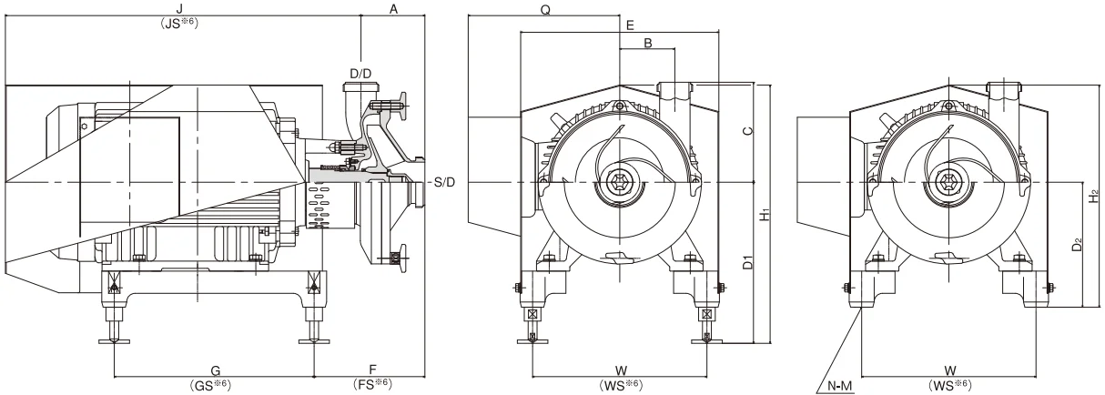
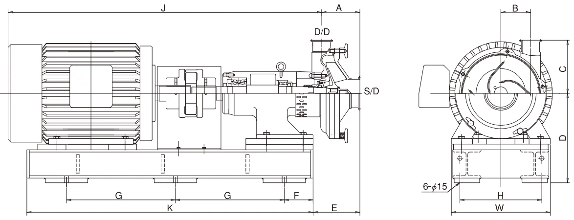
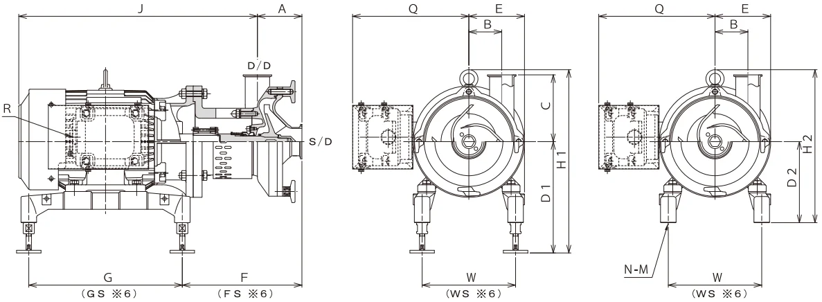
0.75 to 15kW direct-coupled type (integrated motor/shaft type) |
EZtype | |||||||||||||||||||||
| |||||||||||||||||||||
| |||||||||||||||||||||
Type | Dimensions | Motor kW | Dimensions | (mm) | |||||||||||||||||
S/D* | D/D* | A*4 | B | C | F*4 | FS*6 | D1 | D2*5 | H1 | H2*5 | W | WS*6 | E | Q | J | JS*6 | G | GS*6 | N-M | ||
EZN | 2 ½ (2) (1 ½) | 2 (1 ½) | 100*1 | 105.5 | 150*7 | 0.75 | 148.5 | 150.5 | 220 | 150 | 346 | 276 | 145 | 125 | 187 | 182 | 386 | 383 | 290 | 250 | 4-M12 |
1.5~2.2 | 145.5 | 149.5 | 230 | 160 | 357 | 287 | 160 | 140 | 202 | 184 | 411 | 415.5 | 320 | 250 | 4-M12 | ||||||
3.7 | 150.5 | 149.5 | 250 | 182 | 385 | 317 | 210 | 190 | 252 | 209 | 463 | 463 | 345 | 280 | 4-M12 | ||||||
EZM EZH | 3 | 2 (3) | 105 | 99 | 180*2 | 0.75 | 152.5 | 154.5 | 220 | 150(200) | 346 | 276(326) | 145 | 125 | 187 | 182 | 385 | 382 | 290 | 250 | 4-M12 |
1.5~2.2 | 149.5 | 153.5 | 230 | 160(210) | 357 | 287(337) | 160 | 140 | 202 | 184 | 410 | 414.5 | 320 | 250 | 4-M12 | ||||||
3.7 | 154.5 | 153.5 | 250 | 182 | 385 | 317 | 210 | 190 | 252 | 209 | 462 | 462 | 345 | 280 | 4-M12 | ||||||
5.5~7.5 | 208 | - | 290 | 237 | 452 | 399 | 276 | - | 314 | 264 | 521 | - | 260 | - | 4-M12 | ||||||
11~15 | 201.5 | - | 290 | 225 | 485 | 420 | 314 | - | 357 | 291 | 653 | - | 360 | - | 4-M16 | ||||||
EZL | 3 | 2 (3) | 115 | 99 | 180*2 | 1.5~2.2 | 160 | 159 | 230 | 160(210) | 357 | 287(337) | 160 | 140 | 202 | 184 | 410 | 414.5 | 320 | 250 | 4-M12 |
3.7 | 165 | 164 | 250 | 182 | 385 | 317 | 210 | 190 | 252 | 209 | 462 | 462 | 345 | 280 | 4-M12 | ||||||
5.5~7.5 | 218 | - | 290 | 237 | 452 | 339 | 276 | - | 314 | 264 | 521 | - | 260 | - | 4-M12 | ||||||
11~15 | 211.5 | - | 290 | 225 | 485 | 420 | 314 | - | 357 | 291 | 653 | - | 360 | - | 4-M16 | ||||||
EZB | 4 | 2 ½ (4) | 135 | 105.5 | 190*3 | 5.5~7.5 | 228.5 | - | 290 | 237 | 452 | 399 | 276 | - | 314 | 264 | 511 | - | 260 | - | 4-M12 |
11~15 | 222 | - | 290 | 225 | 485 | 420 | 314 | - | 357 | 291 | 643 | - | 360 | - | 4-M16 | ||||||
* S/D shows the suction port diameter and D/D shows the discharge port diameter. * 1 For S/D size of (2) or (1 ½), dimensions A and F increase by +20mm. * 2 For D/D size of (3), dimensions C increases by +40mm. * 3 For D/D size of (4), dimensions C increases by +105mm. * 4 When the pipe end is sanitary flange or JIS 10K flange, dimensions A and F increase by +10mm. *5 Dimensions D2 and H2 in parentheses are for when an optional extension spacer is attached. (If the attachment surface is the whole surface, an extension spacer is required.) * 6 For FS, JS, GS, and WS, SUS304 is employed for the motor base. * 7 For sanitary flange with D/D size of (1 ½), dimension C increases by +10mm. | |||||||||||||||||||||
1.5 to 15kW small-capacity closed impeller pump | |||||||||||||||||
EZHtype | |||||||||||||||||
 | ● Employment of separated-type closed impeller allows you to change EZM type to EZH type by replacing the following 4 parts. ● Achieves stable operations at lower noise (2 to 3dB decrease) and NPSH (0.2 to 0.5m decrease) more efficiently (10 to 50% increase) in low flow rate area. ● Contamination is prevented and impeller finish roughness is good. | ||||||||||||||||
* 1 For high pump heads. SCS16 may be used as the material. * 2 Refer to "(1) Material classification" on Page 14. | 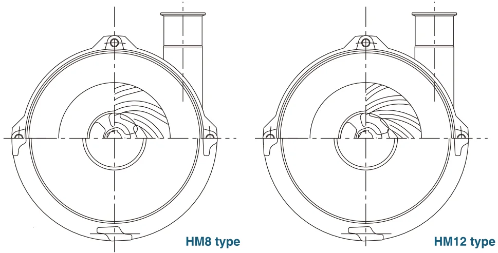 | ||||||||||||||||
22 to 37kW separate type pump | |||||||||||||||||
EStype | |||||||||||||||||
 | Large-capacity bearing-equipped pump (22kW to 37 kW) · Terminal box for 30 to 37kW is mounted on the upper part. · Outdoor-type motor is used for this type as standard. (without motor cover) | ||||||||||||||||
 | |||||||||||||||||
Type | Motor kW | Dimensions | (mm) | ||||||||||||||
S/D* | D/D*1 | A*3 | B | C | D | E | F*3 | G | H | J | K | W | |||||
ESM | 22 | 3 | 2(3) | 105 | 99 | 180 | 316 | 145 | 102 | 385.25 | 290 | 1120 | 1013 | 350 | |||
ESL | 22 | 3 | 2(3) | 115 | 99 | 180*1 | 316 | 155 | 102 | 385.25 | 290 | 1120 | 1013 | 350 | |||
30 | 3 | 2(3) | 115 | 99 | 180*1 | 316 | 155 | 102 | 394.75 | 290 | 1174 | 1013 | 400 | ||||
ESB | 22 | 4 | 2½(4) | 135 | 105.5 | 190*2 | 316 | 165.6 | 102 | 385.25 | 290 | 1110 | 1013 | 350 | |||
30 | 4 | 2½(4) | 135 | 105.5 | 190*2 | 316 | 165.6 | 102 | 394.75 | 290 | 1164 | 1013 | 350 | ||||
37 | 4 | 2½(4) | 135 | 105.5 | 190*2 | 336 | 165.6 | 102 | 382.25 | 330 | 1216 | 1013 | 400 | ||||
* S/D indicates the suction port diameter and D/D indicates the discharge port diameter.
* 1 For D/D size of (3), dimensions C increases by +40mm.
* 2 For D/D size of (4), dimensions C increases by +105mm.
* 3 When the pipe end is sanitary flange or JIS 10K flange, dimensions A and F increase by +10mm.
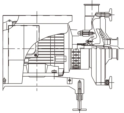
► Cross-section view (EC type) |
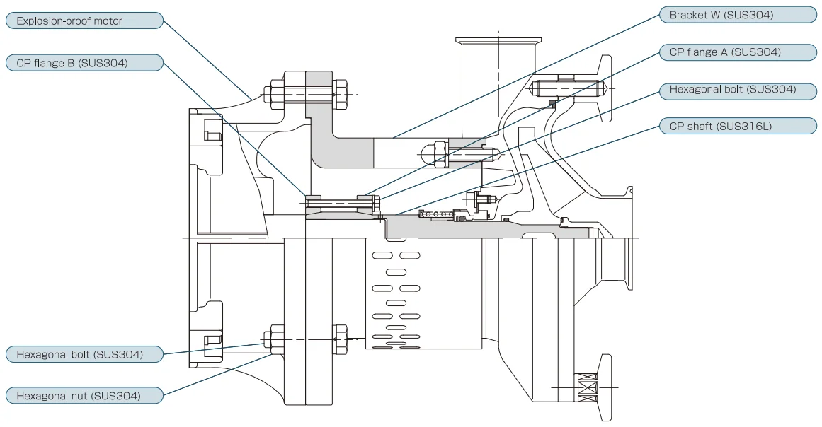 |
1.5 to 7.5kW Coupling type (explosion-proof motor) | ||||||||||||||||||||||
ECtype | ||||||||||||||||||||||
|
Use of explosion-proof motor (d2G4) enables not only energy-saving operation when combined with an inverter but also use in Class I hazardous area. | |||||||||||||||||||||
| ||||||||||||||||||||||
Type | Dimensions | Motor kW | Dimensions | (mm) | ||||||||||||||||||
S/D* | D/D* | A*4 | B | C | F*4 | FS*6 | D1 | D2*5 | H1 | H2*5 | W | WS*6 | E | Q | J | G | GS*6 | N-M | R | |||
EZN | 2 ½ (2) (1 ½) | 2 (1 ½) | 100*1 | 105.5 | 150*7 | 1.5~2.2 | - | 180 | 230 | 160 | 371.3 | 301.3 | - | 140 | 122.5 | 256.3 | 452.4 | - | 250 | 4-M12 | PF ¾ | |
3.7 | 269 | 268 | 250 | 182 | 411.5 | 343.5 | 210 | 190 | 252 | 261 | 536 | 345 | 280 | 4-M12 | PF 1 | |||||||
EZM EZH | 3 | 2 (3) | 105 | 99 | 180*2 | 1.5~2.2 | - | 184 | 230 | 160(210) | 371.3 | 301.3(351.3) | - | 140 | 122.5 | 256.3 | 452.4 | - | 250 | 4-M12 | PF ¾ | |
3.7 | 273 | 272 | 250 | 182 | 411.5 | 343.5 | 210 | 190 | 252 | 261 | 536 | 345 | 280 | 4-M12 | PF 1 | |||||||
5.5~7.5 | 331.5 | - | 290 | 237 | 466.5 | 413.5 | 276 | - | 158 | 320 | 608 | 260 | - | 4-M12 | PF 1¼ | |||||||
EZL | 3 | 2 (3) | 115 | 99 | 180*2 | 1.5~2.2 | - | 194 | 230 | 160(210) | 371.3 | 301.3(351.3) | - | 140 | 122.5 | 256.3 | 452.4 | - | 250 | 4-M12 | PF ¾ | |
3.7 | 283 | 282 | 250 | 182 | 411.5 | 343.5 | 210 | 190 | 252 | 261 | 536 | 345 | 280 | 4-M12 | PF 1 | |||||||
5.5~7.5 | 341.5 | - | 290 | 237 | 466.5 | 413.5 | 276 | - | 158 | 320 | 608 | 260 | - | 4-M16 | PF 1¼ | |||||||
EZB | 4 | 2 ½ (4) | 135 | 105. 5 | 190*3 | 5.5~7.5 | 361.5 | - | 290 | 237 | 466.5 | 413.5 | 276 | - | 158 | 320 | 608 | 260 | - | 4-M12 | PF 1¼ | |
* S/D shows the suction port diameter and D/D shows the discharge port diameter. * 1 For S/D size of (2) or (1 ½), dimensions A and F increase by +20mm. * 2 For D/D size of (3), dimensions C increases by +40mm. * 3 For D/D size of (4), dimensions C increases by +105mm. * 4 When the pipe end is sanitary flange or JIS 10K flange, dimensions A and F increase by +10mm. *5 Dimensions D2 and H2 in parentheses are for when an optional extension spacer is attached. (If the attachment surface is the whole surface, an extension spacer is required.) * 6 For FS, JS, GS, and WS, SUS304 is employed for the motor base. * 7 For sanitary flange with D/D size of (1 ½), dimension C increases by +10mm. | ||||||||||||||||||||||
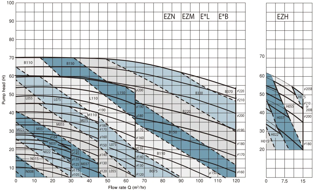
Sanitary pump characteristics table | |
Tolerance | |
ISO 2548 Q ± 8% ISO 2548 Q ± 6% | |
50Hz (2E) | |
 | |
 | |
Characteristics data conditions | Pump piping |
· Fluid: Fresh water at 15°C · Suction port diameter x discharge port diameter N: 2.5s x 2s M: 3s x 2s L: 3s x 2s B: 4s x 2.5s · Rotation speed: Actual rotation speed at each motor capacity · Suction water head: 1 to 2m (G) | · Set the flow rate of suction piping to 1m/s or less. · Perform flow rate adjustment with the inverter or discharge throttle valve not with suction-side throttle valve.
|
Handling of viscous fluid | |
Tolerance | |
ISO 2548 Q ± 8% ISO 2548 Q ± 6% | |
60Hz (2W) | |
 | |
 | |
Handling of viscous fluids | Note |
· In the case of viscous fluids, it is necessary to compensate for the viscosity. Fill out necessary items in the specifications on Page 13 and contact our company. · The viscosity that can be handled is 300mPa∙s or less. · Even for viscous fluids, the pump characteristics tests are conducted by conversion to water equivalent values. | · Select a motor with wide margin. · For quenching mechanism and double mechanism. It is necessary to add 0.3 to 0.5kW to this characteristics table. · When operating in the low-flow-rate area (5m3/h or less), fluid may become heated. · Be sure to operate at positive pressure at the suction side as a rule.
|
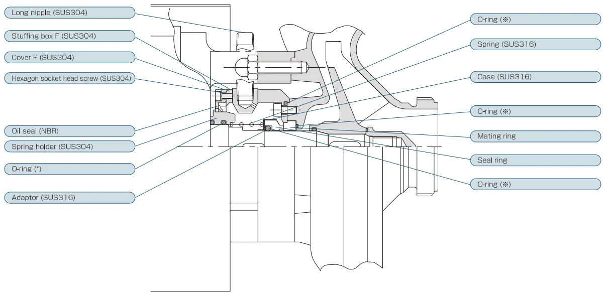
Mechanical seal and maintenance jig |
· An outside system clutch type that can withstand reversing during backwash and is sanitary. · Maintenance cost is low because only sliding part is replaced · Should be used with a suction head of within 0.5MPa. |
► Standard type |
 |
► Quenching type |
· Since a stuffing box is provided to prevent quenching water from scattering. If back pressure is applied to the deain side, leakage may occur from each connection part. · Use water at 0.5 to 1.0 l/min at normal temperature as quenching water. |
* Refer to "(1) Material classification" on Page 14. |
Mechanical seal and maintenance jig | ||||||
► Double mechanical seal type | ||||||
· Allowable leakage amount from each mechanical seal is 3 ml/hr. · Seal fluid pressure should be applied at in-pump pressure or less. | ||||||
* Refer to "(1) Material classification" on Page 14. | ||||||
► Mechanical seal selection standards | ||||||
Material | Fluid properties (upper limit) | Item | ||||
Temperature | Slurry | Viscosity | ||||
Carbon x Ceramic | (1) | -10~120°C | ≤ 0.3% | ≤ 300cp | - | |
Ceramic x Ceramic | (1) | -10~60°C | 0.3~1% | ≤ 300cp | - | |
(2) | >60°C | 0.3~1% | ≤ 300cp | Need to undergo quenching (external cooling). | ||
Superhard x Superhard | (1) | -10~60°C | 0.3~0.8% | ≤ 250cp | - | |
(2) | >60°C | 0.3~0.8% | ≤ 250cp | Need to undergo quenching (external cooling). | ||
Carbon x Ceramic | (1) | >90°C | >0.3% | ≤ 300cp | Need to undergo flushing by double mechanical seal. | |
Ceramic x Ceramic | (2) | >60°C | >1% | ≤ 250cp | ||
Superhard x Superhard | (3) | >60°C | >0.8% | ≤ 250cp | ||
Remarks | Allowable leakage amount of mechanical seal is 3ml/hr | |||||
Maintenance jig (option) | ||||||
Pump shaft cover | Impeller securing jig | Impeller nut attachment/detachment jig | ||||
· Prevents mechanical seal from being broken during disassembly and reassembly. | · Use this jig to secure the impeller. | · Use this jig to disassemble and reassemble the impeller nut. | ||||
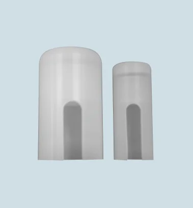 | 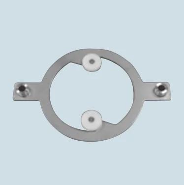 | 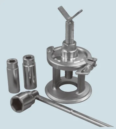 | ||||
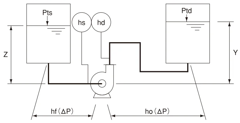
Important points for pump selection and operation | ||||||||||||||||||||||||||
► Pump head and capacity calculation | ||||||||||||||||||||||||||
· Overestimation in pressure loss in the piping line may cause motor overload. · Underestimation in pressure loss in the piping line may cause insufficient in capacity
· Total pump head = discharge pump head - suction pump head. · In the case of viscous fluid (10mPa∙s or higher), compensate for the viscosity to determine the motor power. · Since back wash causes larger pressure loss and pump reversing, provide a bypass circuit. | ||||||||||||||||||||||||||
► Suction characteristics | ||||||||||||||||||||||||||
· If the suction pump head is negative and the liquid temperature is too high, cavitation may occur.
· If gas is mixed in on the suction side, mixed gas/liquid operation will be performed, which will causes the performance to decrease. · In the case of NPSH (A) < NPSH (R), consult our company. This problem can be improved in some cases by inducer, etc. | ||||||||||||||||||||||||||
► Installation and operation | ||||||||||||||||||||||||||
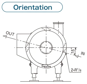
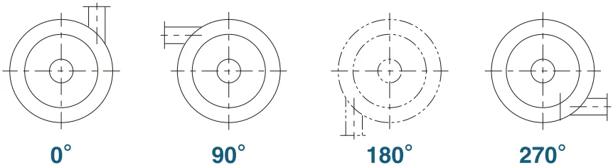
· The following 4 pump discharge port directions are available; however, the pump should be attached at 0° as much as possible. (In cases other than 0° and 90°, cavities may be generated in the upper part of the casing. An air vent is required.) · Be sure to check the pump rotation direction. The anti-clockwise direction when viewed from the front side is the correct direction. · Starting and stopping large-capacity pumps (5.5kW or higher) may affect the service life of each component adversely. (In this case, it is recommended to perform inverter-based starting and λ-∆ startup at least.) · Avoid idling. · Be sure to operate with the pump cover attached. · For pumps of 3.7kW or less, the pump discharge port cannot be attached at 180°. | ||||||||||||||||||||||||||
► Motor rating table | ||||||||||||||||||||||||||
Efficiency | Frame No. | Insulation | Capacity kW | Number of poles | 200V/50Hz | 200V/60Hz | 220V/60Hz | Bearing No. | ||||||||||||||||||
rpm | A | rpm | A | rpm | A | BRG.D.S | BRG.O.S | |||||||||||||||||||
IE3 | 80 | F | 0.75 | 2 | 2900 | 3.2 | 3485 | 2.9 | 3505 | 2.9 | 6207ZZ-C3 | 6204ZZ-C3 | ||||||||||||||
90L | 1.5 | 2 | 2895 | 5.8 | 3470 | 5.6 | 3495 | 5.2 |
6205ZZ-C3 | |||||||||||||||||
2.2 | 2 | 2880 | 8.2 | 3460 | 8 | 3495 | 7.4 | |||||||||||||||||||
112NM | 3.7 | 2 | 2930 | 14.6 | 3510 | 13.8 | 3530 | 12.8 | 6306ZZ-C3 | |||||||||||||||||
132S | 5.5 | 2 | 2930 | 21.6 | 3520 | 20.4 | 3530 | 19 | 6310ZZ-C3 | |||||||||||||||||
7.5 | 2 | 2915 | 27.6 | 3500 | 27 | 3525 | 24.6 | |||||||||||||||||||
160M | 11 | 2 | 2945 | 40 | 3535 | 39 | 3550 | 36 | 6307ZZ-C3 | |||||||||||||||||
15 | 2 | 2945 | 54 | 3535 | 52 | 3550 | 48 | |||||||||||||||||||
180M | 22 | 2 | 2960 | 76 | 3550 | 76 | 3560 | 70 | 6311ZZ-C3 | 6309ZZ-C3 | ||||||||||||||||
180L | 30 | 2 | 2955 | 102 | 3545 | 102 | 3555 | 92 | 6312ZZ-C3 | |||||||||||||||||
200LB | 37 | 2 | 2965 | 128 | 3555 | 126 | 3565 | 116 | 6312ZZ-C3 | |||||||||||||||||
IE1 | Explosion-proof 90L | B | 1.5 | 2 | 2870 | 6.2 | 3440 | 6 | 3450 | 5.6 | 6205ZZ | 6204ZZ | ||||||||||||||
2.2 | 2 | 2860 | 8.6 | 3430 | 8.4 | 34690 | 7.8 | |||||||||||||||||||
Explosion-proof 112M | 3.7 | 2 | 2910 | 14.2 | 3480 | 13.8 | 3490 | 12.8 | 6207ZZ | 6206ZZ | ||||||||||||||||
Explosion-proof 132S | 5.5 | 2 | 2910 | 21.4 | 3490 | 20.2 | 3500 | 19 | 6308ZZ | 6207ZZ | ||||||||||||||||
Sanitary pump specifications
1 | 1) Liquid name | j | 6 | Motor type | Fully-closed external fan | ||||||||||||||||||||
Liquid quality | k | Motor type | Motor capacity |
| |||||||||||||||||||||
2) Specific gravity γ | j | Number of motor poles | 2 4 Other ( ) | ||||||||||||||||||||||
k | Protection structure | Indoor, Outdoor, Other ( ) | |||||||||||||||||||||||
3) Viscosity ν | j mPa∙s | Insulation | F, B ( ) | ||||||||||||||||||||||
k mPa∙s | Installation environment | °C % | |||||||||||||||||||||||
4) Temperature T | j °C |
|
| ||||||||||||||||||||||
k °C | 7 | Drain nozzle | Unnecessary Necessary | ||||||||||||||||||||||
5) Slurry | jApplicable Not applicable ( %) | Options/accessories | Air release nozzle | Unnecessary Necessary | |||||||||||||||||||||
k Applicable Not applicable ( %) | Phase coupling | Unnecessary Necessary | |||||||||||||||||||||||
Remarks |
| Pressure gauge | Unnecessary Necessary | ||||||||||||||||||||||
|
| Foundation bolt | Unnecessary Necessary | ||||||||||||||||||||||
2 | 1) Discharge amount Q | j m3/hr |
|
| |||||||||||||||||||||
Performance | k m3/hr |
|
| ||||||||||||||||||||||
2) Total pump head H | j m |
|
| ||||||||||||||||||||||
k m |
|
| |||||||||||||||||||||||
3) Discharge pump head hd | j m |
|
| ||||||||||||||||||||||
k m |
H=hd-hs hd=ho+Y+Ptd-10.3 hs=Pts-10.3+Z-hf Pvp: Saturated steam pressure (mAbs)
| ||||||||||||||||||||||||
4) Suction pump head hs | j m | ||||||||||||||||||||||||
k m | |||||||||||||||||||||||||
| Remarks |
| |||||||||||||||||||||||
|
| ||||||||||||||||||||||||
3 | 1) Metal liquid contact part | SUS316 SUS304 | |||||||||||||||||||||||
Material | 2) Packing | EPDM, FKM, SE72 | |||||||||||||||||||||||
3) O-ring | EPDM, FKM, SE72 | ||||||||||||||||||||||||
4) Mechanical seal | SC, SS, TT | ||||||||||||||||||||||||
4 | 1) Pump type | Vortex | |||||||||||||||||||||||
Structure | 2) Impeller type | Semi-closed | |||||||||||||||||||||||
3) Casing type | Back-volute | ||||||||||||||||||||||||
4) Mechanical seal type | Clutch type outside | ||||||||||||||||||||||||
5) Mechanical seal | Single Quenching Double | ||||||||||||||||||||||||
6) Discharge direction | ( ) | ||||||||||||||||||||||||
7) Installation method | Floor-mounted, Foundation, For unit | ||||||||||||||||||||||||
5 | 1) Voltage | 200V 220V Other ( V) | |||||||||||||||||||||||
Power Supply | 2) Frequency | 50Hz 60Hz Other ( V) | |||||||||||||||||||||||
3) Use of inverter | Used Unused | ||||||||||||||||||||||||
4) Location of use | Indoor Outdoor | ||||||||||||||||||||||||
Sanitary pump specifications
1 | Material classification | |||
Symbol | Material | |||
Metal part (main body) | Casing packing | O-ring | ||
316 | SUS316L | Silicone rubber | Fluororubber | |
316-E | SUS316L | EPDM | EPDM | |
316-F | SUS316L | Fluororubber | Fluororubber | |
316-S | SUS316L | Silicone rubber | Silicone rubber | |
304 | SUS304 | Silicone rubber | Fluororubber | |
304-E | SUS304 | EPDM | EPDM | |
304-F | SUS304 | Fluororubber | Fluororubber | |
304-S | SUS304 | Silicone rubber | Silicone rubber | |
* For 304 material, only N, M, and L size are available as (8) impeller diameter classification. | ||||
2 | Motor base material | ||
Category | Symbol | Material | |
Standard | - | FC20 | |
Special | S | SUS304 | |
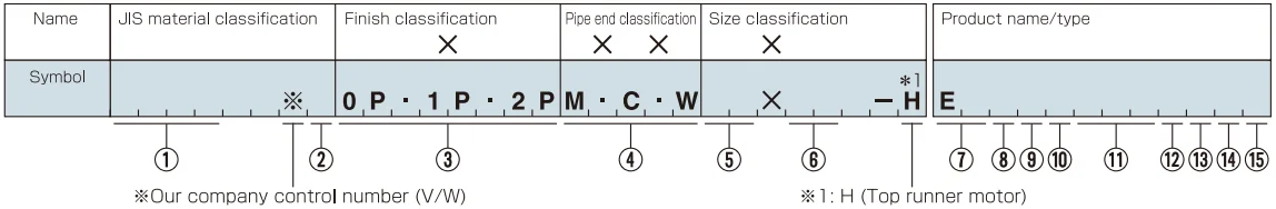
3 | Finish classification | |||
Category | Symbol | Finish | ||
Internal finish | External finish | |||
Standard | 0P | Pickling | Pickling or beads shot blast | |
1P | #320 to #400 buff polished finish | Pickling or beads shot blast | ||
Option | EP (1P) | Electrolytic polishing finish | Pickling or beads shot blast | |
ODP | Special | Special | ||
4 | Pipe end classification | ||
Category | Symbol | Details | |
Standard | M | ISO male | |
C | ISO clamp | ||
Optional | N | ISO nut | |
T | Sanitary flange | ||
Special | X | - | |
5 6 | Size classification | |
Symbol | Size | |
15 | 1 ½ S | |
20 | 2S | |
25 | 2 ½ S | |
30 | 3S | |
40 | 4S | |
Suction x discharge | ||
7 | Basic model classification | |
Symbol | Details | Note |
EZ | Direct-connection (motor/shaft integrated type) | Standard |
ES | Separate type | Standard |
EC | Direct-connection (Coupling method) | Explosion-proof |
* For EC, 1.5 to 7.5kW is output. | ||
8 | Impeller diameter classification | |
Symbol | Impeller diameter | |
B | 220 | |
L | 200 | |
M | 200 | |
N | 165 | |
H | 210 | |
9 | Number of motor poles | |||
Category | Symbol | Number of poles | Rotation number (r.p.m) | |
Standard | 2 | 2P | 50Hz (2915) 60Hz(3500) | |
Optional | 4 | 4P*1 | 50Hz (1460) 60Hz (1750) | |
* For 4P motor, the performance may vary significantly. Consult with our company. | ||||
* For 4P, 3.7 to 15kW is output | ||||
10 | Frequency classification | |
Symbol | Frequency (Hz) | |
E | 50 | |
W | 60 | |
X | Other | |
11 | Motor capacity (kW) classification | |||
Symbol | Motor capacity kW | Symbol | Motor capacity kW | |
008 | 0.75 | 110 | 11 | |
015 | 1.5 | 150 | 15 | |
022 | 2.2 | 220 | 22 | |
037 | 3.7 | 300 | 30 | |
055 | 5.5 | 370 | 37 | |
075 | 7.5 |
| ||
12 | Motor type classification | ||
Category | Symbol | Symbol | |
Standard | B | 200/220V 50/60Hz indoor type | |
Optional | O | 200/220V 50/60Hz outdoor type | |
C | Various voltages | ||
P | Outdoor type various voltages | ||
Explosion-proof | Z | 200/220V 50/60Hz outdoor type | |
13 | Mechanical seal type | |
Symbol | Details | |
S | Single mechanical | |
C | Quenching mechanical seal | |
Q | Double mechanical seal | |
14 | Mechanical seal classification | ||
Category | Symbol | Details | |
Standard | C | Carbon x ceramic (M6-CxES-4) | |
Optional | S | Ceramic x ceramic (ES-4xES-4) | |
T | Superhard x superhard (TC3 x TC3) | ||
Special | X | Other | |
* Symbols in parentheses are manufacturer’s symbols. | |||
15 | Options | |
Symbol | Details | |
D | With drain nozzle | |
A | With air release nozzle | |
S | With air release and drain nozzle | |
U | With base for unit | |
X | Other | |
Đánh giá sản phẩm của chúng tôi