SH6000 SeriesSBC Pressure Balanced Stem and Cage Guiding Perforated Plug Type | |||||||||||||||||||||||||||||||||||||||||||||||||||||||||||||||||||||||||||||||||||||||||||||||||||||||||||||||||||||||||||||||||||||||||||||||||||||||||||||||||||||||||||||||||||||||||||||||||||||||||||||||||||||||||||||||||||||||||||||||||||||||||||||||||||||||||||||||||||||||||||||||||||||||||||||||||||||||||||||||||||||||||||||||||||||||||||||||||||||||||||||||||||||||||||||||||||||||||||||||
Guided by big area of busing and cage, working trims are of dynamic stability. The series is characterized by balanced trims require for very high pressure drops. Only need smaller thrust force to reliably modulate. Perforated cylinder plug can effectively protect sealing surface of seat to be damaged by high speed flow scoured. Combined with complex piston rings, it also presents excellent seal performance. SBC series suits normal and heavy duty applications. | 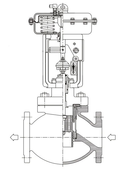 | ||||||||||||||||||||||||||||||||||||||||||||||||||||||||||||||||||||||||||||||||||||||||||||||||||||||||||||||||||||||||||||||||||||||||||||||||||||||||||||||||||||||||||||||||||||||||||||||||||||||||||||||||||||||||||||||||||||||||||||||||||||||||||||||||||||||||||||||||||||||||||||||||||||||||||||||||||||||||||||||||||||||||||||||||||||||||||||||||||||||||||||||||||||||||||||||||||||||||||||||
Valve Body | |||||||||||||||||||||||||||||||||||||||||||||||||||||||||||||||||||||||||||||||||||||||||||||||||||||||||||||||||||||||||||||||||||||||||||||||||||||||||||||||||||||||||||||||||||||||||||||||||||||||||||||||||||||||||||||||||||||||||||||||||||||||||||||||||||||||||||||||||||||||||||||||||||||||||||||||||||||||||||||||||||||||||||||||||||||||||||||||||||||||||||||||||||||||||||||||||||||||||||||||
Type: Cast globe Valve Nominal Size: DN80, 100, 150, 200, 250, 300, 350, 400 Nominal Pressure: ANSI 150, 300 DIN PN16, 25, 40 JIS 10K, 20K 30K GB PN1.6, 2.5, 4.0 MPa End Connection: Flange ANSI B16.5 RF, RTJ DIN2543/2544/2545 RF JISB2201 RF JB/T81 RF JB/T82.2 FM | |||||||||||||||||||||||||||||||||||||||||||||||||||||||||||||||||||||||||||||||||||||||||||||||||||||||||||||||||||||||||||||||||||||||||||||||||||||||||||||||||||||||||||||||||||||||||||||||||||||||||||||||||||||||||||||||||||||||||||||||||||||||||||||||||||||||||||||||||||||||||||||||||||||||||||||||||||||||||||||||||||||||||||||||||||||||||||||||||||||||||||||||||||||||||||||||||||||||||||||||
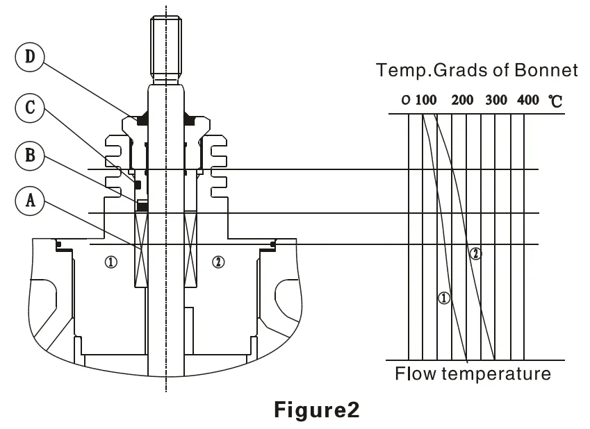
Weld ANSI B16.5; BW Face to Face Dimension: ANSI150RF, JIS10K ( IEC60534-3-1 37 Series ) ANSI300RF, JIS20K, JIS30K ( IEC60534-3-1 38 Series ) ANSI150/300 RTJ ( ASME B16.10 CLASS 150/300RTJ ) DIN PN16, 25, 40 ( DIN3202-F1 ) GB PN1.6, 2.5, 4.0 MPa ( ISO5752 1 Series ) Please refer to table 6.1~6.2 Body Material: Please refer to table1 Please refer to figure 3 for Operated Temp.&Pressure Range Bonnet Type: STD type·········-46°C ~ 200°C ; 200°C ~ 300°C Radiation fin type·········300°C ~ 530°C Please pay attention to the different Temp.&Pressure Range of material Packing Material: PTFE V-ring compound packing, graphite compound packing, graphite packing Operating Temp.&Pressure range is shown in table 2, figure2 Seal Gasket: Spiral wound gasket ( PTFE+316, Flexible Graphite+316 ) Graphite with metal gasket ( Graphite+316, Graphite+304 ) Valve Trim Plug Type: Perforated cylinder plug Flow Characteristic: EQ%, Linearity ( Please refer to figure4 ) Trim Material: Please refer to table 3 for STD material assembly, operated Temp.&Pressure Range Actuator Type: Multi-spring diaphragm Air Supply: Max. 6bar Ambient Temp.: -20°C+80°C Spring range: As shown in Table 5 Air Connection: G1/8 ( SA1 ) ; G1/4 ( SA2 ) ; G3/4 ( SA3 ) STD Specification: As shown in Table 5 | |||||||||||||||||||||||||||||||||||||||||||||||||||||||||||||||||||||||||||||||||||||||||||||||||||||||||||||||||||||||||||||||||||||||||||||||||||||||||||||||||||||||||||||||||||||||||||||||||||||||||||||||||||||||||||||||||||||||||||||||||||||||||||||||||||||||||||||||||||||||||||||||||||||||||||||||||||||||||||||||||||||||||||||||||||||||||||||||||||||||||||||||||||||||||||||||||||||||||||||||
Accessory Positioner, Filter-regulator valve, Solenoid valve, Limit switch, Valve position Transmitter, Booster relay, Lock-valve, Handwheel, etc. Action Air to open, Air to close Performance Rangeability: 50:1 Seat leakage: Metal seal is according to ANSI B16.104 ClassIV Hysteresis: 3% ( Without Positioner ) 1% ( With Positioner ) Linearity: ± 5% ( Without Positioner ) ±1% ( With Positioner ) Rated CV: As shown in table 4 Allowable pressure differential: As shown in table 5 Figure Size: As shown in figure5, table 6.1~6.2 Weight of product: As shown in table 6.1~6.2 Performance Special inspection
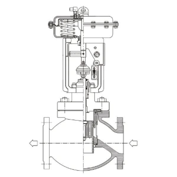
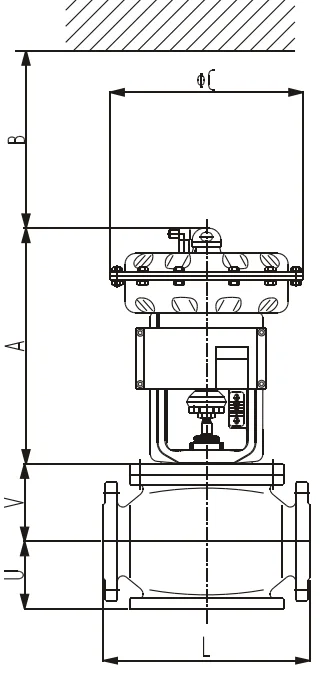
Body Assembly Structure ( As shown in figure 1 ) | |||||||||||||||||||||||||||||||||||||||||||||||||||||||||||||||||||||||||||||||||||||||||||||||||||||||||||||||||||||||||||||||||||||||||||||||||||||||||||||||||||||||||||||||||||||||||||||||||||||||||||||||||||||||||||||||||||||||||||||||||||||||||||||||||||||||||||||||||||||||||||||||||||||||||||||||||||||||||||||||||||||||||||||||||||||||||||||||||||||||||||||||||||||||||||||||||||||||||||||||
Notable Characteristics
| 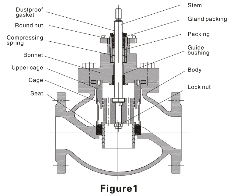 | ||||||||||||||||||||||||||||||||||||||||||||||||||||||||||||||||||||||||||||||||||||||||||||||||||||||||||||||||||||||||||||||||||||||||||||||||||||||||||||||||||||||||||||||||||||||||||||||||||||||||||||||||||||||||||||||||||||||||||||||||||||||||||||||||||||||||||||||||||||||||||||||||||||||||||||||||||||||||||||||||||||||||||||||||||||||||||||||||||||||||||||||||||||||||||||||||||||||||||||||
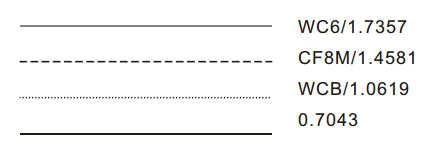
Table 1 Body material
| |||||||||||||||||||||||||||||||||||||||||||||||||||||||||||||||||||||||||||||||||||||||||||||||||||||||||||||||||||||||||||||||||||||||||||||||||||||||||||||||||||||||||||||||||||||||||||||||||||||||||||||||||||||||||||||||||||||||||||||||||||||||||||||||||||||||||||||||||||||||||||||||||||||||||||||||||||||||||||||||||||||||||||||||||||||||||||||||||||||||||||||||||||||||||||||||||||||||||||||||
Table 2 Applicable Temp.&Pressure range of packing material
Note: please choose the most related Temp.Range
| |||||||||||||||||||||||||||||||||||||||||||||||||||||||||||||||||||||||||||||||||||||||||||||||||||||||||||||||||||||||||||||||||||||||||||||||||||||||||||||||||||||||||||||||||||||||||||||||||||||||||||||||||||||||||||||||||||||||||||||||||||||||||||||||||||||||||||||||||||||||||||||||||||||||||||||||||||||||||||||||||||||||||||||||||||||||||||||||||||||||||||||||||||||||||||||||||||||||||||||||
ASME B16.35 150/300
Temp. | ASME B16.34/B16.35 | ||||||||||||||||||||||||||||||||||||||||||||||||||||||||||||||||||||||||||||||||||||||||||||||||||||||||||||||||||||||||||||||||||||||||||||||||||||||||||||||||||||||||||||||||||||||||||||||||||||||||||||||||||||||||||||||||||||||||||||||||||||||||||||||||||||||||||||||||||||||||||||||||||||||||||||||||||||||||||||||||||||||||||||||||||||||||||||||||||||||||||||||||||||||||||||||||||||||||||||||
| ASME B16.34 600/900/1500
Temp. | ||||||||||||||||||||||||||||||||||||||||||||||||||||||||||||||||||||||||||||||||||||||||||||||||||||||||||||||||||||||||||||||||||||||||||||||||||||||||||||||||||||||||||||||||||||||||||||||||||||||||||||||||||||||||||||||||||||||||||||||||||||||||||||||||||||||||||||||||||||||||||||||||||||||||||||||||||||||||||||||||||||||||||||||||||||||||||||||||||||||||||||||||||||||||||||||||||||||||||||||
DIN EN 1092-1 PN16, PN25, PN40
Temp. | DIN EN 1092-1 | ||||||||||||||||||||||||||||||||||||||||||||||||||||||||||||||||||||||||||||||||||||||||||||||||||||||||||||||||||||||||||||||||||||||||||||||||||||||||||||||||||||||||||||||||||||||||||||||||||||||||||||||||||||||||||||||||||||||||||||||||||||||||||||||||||||||||||||||||||||||||||||||||||||||||||||||||||||||||||||||||||||||||||||||||||||||||||||||||||||||||||||||||||||||||||||||||||||||||||||||
 | DIN EN 1092-1 PN63, PN100, PN160, PN250
Temp. | ||||||||||||||||||||||||||||||||||||||||||||||||||||||||||||||||||||||||||||||||||||||||||||||||||||||||||||||||||||||||||||||||||||||||||||||||||||||||||||||||||||||||||||||||||||||||||||||||||||||||||||||||||||||||||||||||||||||||||||||||||||||||||||||||||||||||||||||||||||||||||||||||||||||||||||||||||||||||||||||||||||||||||||||||||||||||||||||||||||||||||||||||||||||||||||||||||||||||||||||
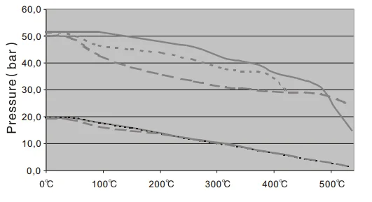
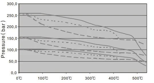
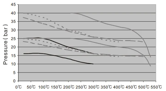
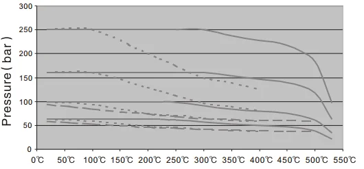
Figure 3 Temp.&Pressure curve | |||||||||||||||||||||||||||||||||||||||||||||||||||||||||||||||||||||||||||||||||||||||||||||||||||||||||||||||||||||||||||||||||||||||||||||||||||||||||||||||||||||||||||||||||||||||||||||||||||||||||||||||||||||||||||||||||||||||||||||||||||||||||||||||||||||||||||||||||||||||||||||||||||||||||||||||||||||||||||||||||||||||||||||||||||||||||||||||||||||||||||||||||||||||||||||||||||||||||||||||
Table 3 STD Material Assembly, Operated Temp.&Pressure Range of Trim
Harden treatment: Hard chrome plated, Stellite surface, Heat treatment, Nitriding treatment, Spray tungsten carbide, etc. | |||||||||||||||||||||||||||||||||||||||||||||||||||||||||||||||||||||||||||||||||||||||||||||||||||||||||||||||||||||||||||||||||||||||||||||||||||||||||||||||||||||||||||||||||||||||||||||||||||||||||||||||||||||||||||||||||||||||||||||||||||||||||||||||||||||||||||||||||||||||||||||||||||||||||||||||||||||||||||||||||||||||||||||||||||||||||||||||||||||||||||||||||||||||||||||||||||||||||||||||
Table 4 Rated Cv.
| |||||||||||||||||||||||||||||||||||||||||||||||||||||||||||||||||||||||||||||||||||||||||||||||||||||||||||||||||||||||||||||||||||||||||||||||||||||||||||||||||||||||||||||||||||||||||||||||||||||||||||||||||||||||||||||||||||||||||||||||||||||||||||||||||||||||||||||||||||||||||||||||||||||||||||||||||||||||||||||||||||||||||||||||||||||||||||||||||||||||||||||||||||||||||||||||||||||||||||||||
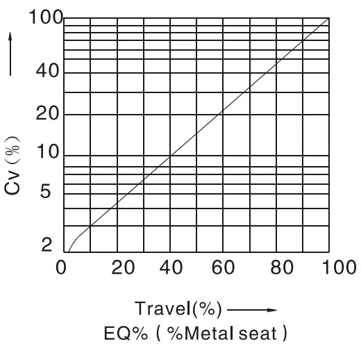 | 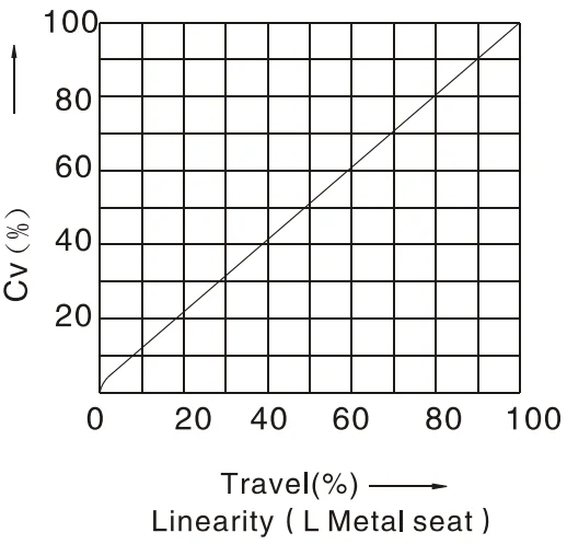 | ||||||||||||||||||||||||||||||||||||||||||||||||||||||||||||||||||||||||||||||||||||||||||||||||||||||||||||||||||||||||||||||||||||||||||||||||||||||||||||||||||||||||||||||||||||||||||||||||||||||||||||||||||||||||||||||||||||||||||||||||||||||||||||||||||||||||||||||||||||||||||||||||||||||||||||||||||||||||||||||||||||||||||||||||||||||||||||||||||||||||||||||||||||||||||||||||||||||||||||||
Figure4 Flow characteristic curve | |||||||||||||||||||||||||||||||||||||||||||||||||||||||||||||||||||||||||||||||||||||||||||||||||||||||||||||||||||||||||||||||||||||||||||||||||||||||||||||||||||||||||||||||||||||||||||||||||||||||||||||||||||||||||||||||||||||||||||||||||||||||||||||||||||||||||||||||||||||||||||||||||||||||||||||||||||||||||||||||||||||||||||||||||||||||||||||||||||||||||||||||||||||||||||||||||||||||||||||||
Table 5 Allowable pressure diferential (Leakage classIV)
| |||||||||||||||||||||||||||||||||||||||||||||||||||||||||||||||||||||||||||||||||||||||||||||||||||||||||||||||||||||||||||||||||||||||||||||||||||||||||||||||||||||||||||||||||||||||||||||||||||||||||||||||||||||||||||||||||||||||||||||||||||||||||||||||||||||||||||||||||||||||||||||||||||||||||||||||||||||||||||||||||||||||||||||||||||||||||||||||||||||||||||||||||||||||||||||||||||||||||||||||
Continued Table 5
Note: 1 .”Ö” stands for bolt and nut impacted yoke ( Nor. Temp. ) , the rest is round nut impacted yoke ( Nor. Temp.or High Temp. ) .
| |||||||||||||||||||||||||||||||||||||||||||||||||||||||||||||||||||||||||||||||||||||||||||||||||||||||||||||||||||||||||||||||||||||||||||||||||||||||||||||||||||||||||||||||||||||||||||||||||||||||||||||||||||||||||||||||||||||||||||||||||||||||||||||||||||||||||||||||||||||||||||||||||||||||||||||||||||||||||||||||||||||||||||||||||||||||||||||||||||||||||||||||||||||||||||||||||||||||||||||||
| | ||||||||||||||||||||||||||||||||||||||||||||||||||||||||||||||||||||||||||||||||||||||||||||||||||||||||||||||||||||||||||||||||||||||||||||||||||||||||||||||||||||||||||||||||||||||||||||||||||||||||||||||||||||||||||||||||||||||||||||||||||||||||||||||||||||||||||||||||||||||||||||||||||||||||||||||||||||||||||||||||||||||||||||||||||||||||||||||||||||||||||||||||||||||||||||||||||||||||||||||
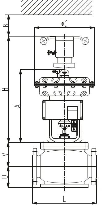
Figure5 DN80~DN400 ( 3"~16" ) | |||||||||||||||||||||||||||||||||||||||||||||||||||||||||||||||||||||||||||||||||||||||||||||||||||||||||||||||||||||||||||||||||||||||||||||||||||||||||||||||||||||||||||||||||||||||||||||||||||||||||||||||||||||||||||||||||||||||||||||||||||||||||||||||||||||||||||||||||||||||||||||||||||||||||||||||||||||||||||||||||||||||||||||||||||||||||||||||||||||||||||||||||||||||||||||||||||||||||||||||
Table 6.1 Figure size (mm)&Weight (Kg) ( DN80 ~ DN400, DIN PN16/25/40)
Note: Weight=Body assembly+Actuator ( without handwheel ) | |||||||||||||||||||||||||||||||||||||||||||||||||||||||||||||||||||||||||||||||||||||||||||||||||||||||||||||||||||||||||||||||||||||||||||||||||||||||||||||||||||||||||||||||||||||||||||||||||||||||||||||||||||||||||||||||||||||||||||||||||||||||||||||||||||||||||||||||||||||||||||||||||||||||||||||||||||||||||||||||||||||||||||||||||||||||||||||||||||||||||||||||||||||||||||||||||||||||||||||||
Table 6.2 Figure size(mm)&Weight (Kg) (3" ~ 16", ANSI150/300)
Note: Weight=Body assembly+Actuator ( without handwhell ) | |||||||||||||||||||||||||||||||||||||||||||||||||||||||||||||||||||||||||||||||||||||||||||||||||||||||||||||||||||||||||||||||||||||||||||||||||||||||||||||||||||||||||||||||||||||||||||||||||||||||||||||||||||||||||||||||||||||||||||||||||||||||||||||||||||||||||||||||||||||||||||||||||||||||||||||||||||||||||||||||||||||||||||||||||||||||||||||||||||||||||||||||||||||||||||||||||||||||||||||||
Ordering Information Please specify the following information: 1. Type 2. Nominal size 3. Nominal pressure & end connection 4. Body & trim material, harden treatment request 5. Flow characteristic 6. Packing material ( code ) 7. Actuator type, with handwheel or not & Air pressure supply 8. Action type ( Direct or Reverse ) 9. Accessory ( with positioner & Air regulator or not ) 10.Oil-free or Copper-free, etc. 11.Fluid Name & state ( liquid, gas, steam, etc. ) 12.Pipeline size, wall thickness ( Inlet, outlet ) 13.Nor. Flow, Max. flow & Min. flow 14.Flow pressure & Pressure differential 15.( Full open/close ) 16.Flow temp., Gravity or Density 17.Inlet and outlet pressure 18.The Gravity & viscosity of fluid, with slurry, flashing or not 19.Used in high pressure, Temp., &EXP. Condition or not 20. Other special requests | |||||||||||||||||||||||||||||||||||||||||||||||||||||||||||||||||||||||||||||||||||||||||||||||||||||||||||||||||||||||||||||||||||||||||||||||||||||||||||||||||||||||||||||||||||||||||||||||||||||||||||||||||||||||||||||||||||||||||||||||||||||||||||||||||||||||||||||||||||||||||||||||||||||||||||||||||||||||||||||||||||||||||||||||||||||||||||||||||||||||||||||||||||||||||||||||||||||||||||||||
Lưu ý
Sản phẩm Van điều khiển SGC được phát triển liên tục, thông tin có thể có thay đổi mà không kịp thời thông báo đến Quý khách hàng!
Đánh giá sản phẩm của chúng tôi