Mục lục
- SH6000 Series
- SPL Parabolic Plug Low Temperature Type
- Table1 Body material
- Table 2 Applicable Temp.&Pressure range of packing material
- Table 4 Rated Cv.
- Table 5.2 Allowable pressure differential ( Leakage class IV PTFE packing )
- Table 5.3 Allowable pressure differential ( Leakage classIV PTFE packing )
- Table 5.4 Allowable pressure differential ( Leakage classIV Graphite packing )
- Table 6.1 Figure size (mm)&Weight (Kg) ( DN15 ~ DN100, DIN PN16/25/40)
- Table 6.2 Figure size(mm)&Weight (Kg) ( 1/2" ~ 4" , ANSI150/300 )
- Table 6.3 Figure size (mm)&Weight (Kg) ( DN150 ~ DN400, DIN PN16/25/40)
- Table 6.4 Figure size(mm)&Weight (Kg) ( 6" ~ 16" , ANSI150/300 )
SH6000 SeriesSPL Parabolic Plug Low Temperature Type | |||||||||||||||||||||||||||||||||||||||||||||||||||||||||||||||||||||||||||||||||||||||||||||||||||||||||||||||||||||||||||||||||||||||||||||||||||||||||||||||||||||||||||||||||||||||||||||||||||||||||||||||||||||||||||||||||||||||||||||||||||||||||||||||||||||||||||||||||||||||||||||||||||||||||||||||||||||||||||||||||||||||||||||||||||||||||||||||||||||||||||||||||||||||||||||||||||||||||||||||||||||||||||||||||||||||||||
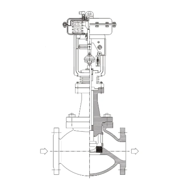
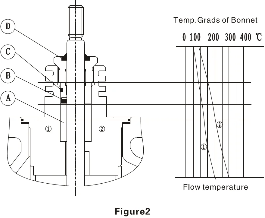
SPL series is specially used in cryogenic services. Valve plug and stem extension are double guided. The bottom guiding is located right below the valve seat. Each part which is subject to wear can be individually replaced, and STP is its base type. The bonnet extension prevents icing of the packing area. The thin walls of the insulation column and of the stem extension allow only a very low conductive heat flow. The bonnet extension length is based on customer requirements. | 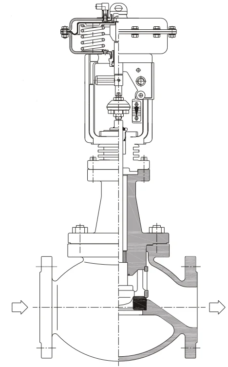 | ||||||||||||||||||||||||||||||||||||||||||||||||||||||||||||||||||||||||||||||||||||||||||||||||||||||||||||||||||||||||||||||||||||||||||||||||||||||||||||||||||||||||||||||||||||||||||||||||||||||||||||||||||||||||||||||||||||||||||||||||||||||||||||||||||||||||||||||||||||||||||||||||||||||||||||||||||||||||||||||||||||||||||||||||||||||||||||||||||||||||||||||||||||||||||||||||||||||||||||||||||||||||||||||||||||||||||
Valve Body | |||||||||||||||||||||||||||||||||||||||||||||||||||||||||||||||||||||||||||||||||||||||||||||||||||||||||||||||||||||||||||||||||||||||||||||||||||||||||||||||||||||||||||||||||||||||||||||||||||||||||||||||||||||||||||||||||||||||||||||||||||||||||||||||||||||||||||||||||||||||||||||||||||||||||||||||||||||||||||||||||||||||||||||||||||||||||||||||||||||||||||||||||||||||||||||||||||||||||||||||||||||||||||||||||||||||||||
Type: Cast globe Valve Nominal Size: DN15, 20, 25, 32, 40, 50, 65, 80, 100, 150, 200, 250, 300 Nominal Pressure: ANSI 150, 300 DIN PN16, 25, 40 JIS 10K, 20K 30K GB PN1.6, 2.5, 4.0 MPa End Connection: Flange ANSI B16.5 RF, RTJ DIN2543/2544/2545 RF JISB2201 RF JB/T81 RF JB/T82.2 FM | |||||||||||||||||||||||||||||||||||||||||||||||||||||||||||||||||||||||||||||||||||||||||||||||||||||||||||||||||||||||||||||||||||||||||||||||||||||||||||||||||||||||||||||||||||||||||||||||||||||||||||||||||||||||||||||||||||||||||||||||||||||||||||||||||||||||||||||||||||||||||||||||||||||||||||||||||||||||||||||||||||||||||||||||||||||||||||||||||||||||||||||||||||||||||||||||||||||||||||||||||||||||||||||||||||||||||||
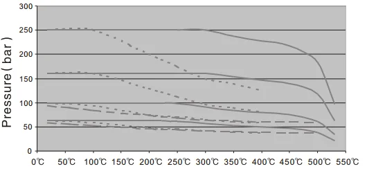
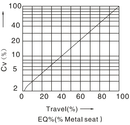
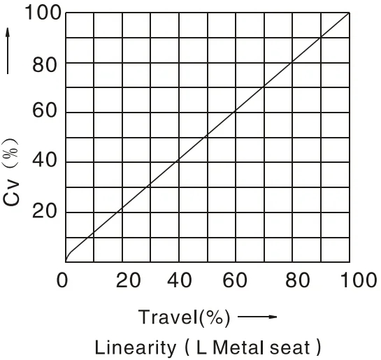
Weld ANSI B16.5 SW ( DN £ 50 ) ; BW ( DN > 50 ) Face to Face Dimension: ANSI150RF, JIS10K ( IEC60534-3-1 37 Series ) ANSI300RF, JIS20K, JIS30K ( IEC60534-3-1 38 Series ) ANSI150/300 RTJ ( ASME B16.10 CLASS 150/300RTJ ) DIN PN16, 25, 40 ( DIN3202-F1 ) GB PN1.6, 2.5, 4.0 MPa ( ISO5752 1 Series ) Please refer to table 5.1~5.4 Body Material: Please refer to table1 Please refer to figure 3 for Operated Temp.&Pressure Range Bonnet Type: Bellows type·········-46°C ~ 350°C Please pay attention to the different Temp.&Pressure Range of material Packing Material: Graphite compound packing, graphite packing, etc. Operating Temp.&Pressure range is shown in table 2, figure2 Seal Gasket: Spiral wound gasket ( PTFE+316, Flexible Graphite+316 ) Graphite with metal gasket ( Graphite+316, Graphite+304 ) Valve Trim Plug Type: Parabolic column plug Flow Characteristic: EQ%, Linearity, quickly opening (Please refer to figure4) Trim Material: Plug 0Cr18Ni12Mo2Ti (316Ti) Nitriding treatment Seat 0Cr18Ni12Mo2Ti (316Ti) Actuator Type: Multi-spring diaphragm Air Supply: Max. 6bar Ambient Temp.: -20°C+80°C Spring range: As shown in Table 4.1 ~ 4.4 Air Connection: G1/8 ( SA1 ) ; G1/4 ( SA2 ) ; G3/4 ( SA3 ) STD Specification: As shown in Table 4.1 ~ 4.4 | |||||||||||||||||||||||||||||||||||||||||||||||||||||||||||||||||||||||||||||||||||||||||||||||||||||||||||||||||||||||||||||||||||||||||||||||||||||||||||||||||||||||||||||||||||||||||||||||||||||||||||||||||||||||||||||||||||||||||||||||||||||||||||||||||||||||||||||||||||||||||||||||||||||||||||||||||||||||||||||||||||||||||||||||||||||||||||||||||||||||||||||||||||||||||||||||||||||||||||||||||||||||||||||||||||||||||||
Accessory Positioner, Filter-regulator valve, Solenoid valve, Limit switch, Valve position Transmitter, Booster relay, Lock-valve, Handwheel, etc. Action Air to open, Air to close Performance Rangeability: 50:1 Seat leakage: According to ANSI B16.104 ClassIV, Class V Hysteresis: 3% ( Without Positioner ) 1% ( With Positioner ) Linearity: ± 5% ( Without Positioner ) ±1% ( With Positioner ) Rated CV: As shown in table 4 Allowable pressure differential: As shown in table 4.1~4.4 Figure Size: As shown in figure5.1, 5.2, table 5.1~5.4 Weight of product: As shown in table 5.1~5.4 Performance Special inspection Flow characteristic test, material test, low temperature test, steam test, non-damages test Special inspection Flow characteristic test, material test, low temperature test, steam test, non-damages test
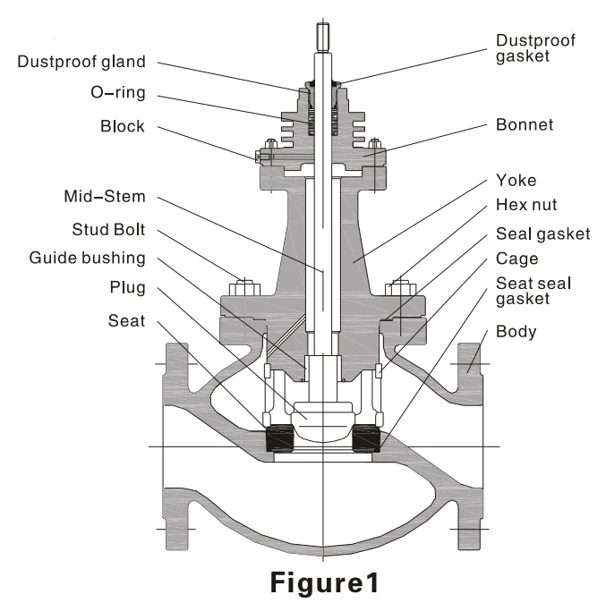
Body Assembly Structure ( As shown in figure 1 ) | |||||||||||||||||||||||||||||||||||||||||||||||||||||||||||||||||||||||||||||||||||||||||||||||||||||||||||||||||||||||||||||||||||||||||||||||||||||||||||||||||||||||||||||||||||||||||||||||||||||||||||||||||||||||||||||||||||||||||||||||||||||||||||||||||||||||||||||||||||||||||||||||||||||||||||||||||||||||||||||||||||||||||||||||||||||||||||||||||||||||||||||||||||||||||||||||||||||||||||||||||||||||||||||||||||||||||||
Performance
| | ||||||||||||||||||||||||||||||||||||||||||||||||||||||||||||||||||||||||||||||||||||||||||||||||||||||||||||||||||||||||||||||||||||||||||||||||||||||||||||||||||||||||||||||||||||||||||||||||||||||||||||||||||||||||||||||||||||||||||||||||||||||||||||||||||||||||||||||||||||||||||||||||||||||||||||||||||||||||||||||||||||||||||||||||||||||||||||||||||||||||||||||||||||||||||||||||||||||||||||||||||||||||||||||||||||||||||
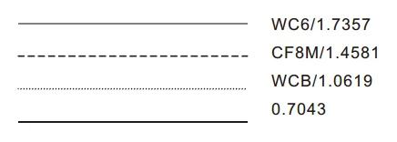
Table1 Body material
| |||||||||||||||||||||||||||||||||||||||||||||||||||||||||||||||||||||||||||||||||||||||||||||||||||||||||||||||||||||||||||||||||||||||||||||||||||||||||||||||||||||||||||||||||||||||||||||||||||||||||||||||||||||||||||||||||||||||||||||||||||||||||||||||||||||||||||||||||||||||||||||||||||||||||||||||||||||||||||||||||||||||||||||||||||||||||||||||||||||||||||||||||||||||||||||||||||||||||||||||||||||||||||||||||||||||||||
Table 2 Applicable Temp.&Pressure range of packing material
Note: please choose the most related Temp.Range
| |||||||||||||||||||||||||||||||||||||||||||||||||||||||||||||||||||||||||||||||||||||||||||||||||||||||||||||||||||||||||||||||||||||||||||||||||||||||||||||||||||||||||||||||||||||||||||||||||||||||||||||||||||||||||||||||||||||||||||||||||||||||||||||||||||||||||||||||||||||||||||||||||||||||||||||||||||||||||||||||||||||||||||||||||||||||||||||||||||||||||||||||||||||||||||||||||||||||||||||||||||||||||||||||||||||||||||
ASME B16.35 150/300
Temp. | ASME B16.34/B16.35 | ||||||||||||||||||||||||||||||||||||||||||||||||||||||||||||||||||||||||||||||||||||||||||||||||||||||||||||||||||||||||||||||||||||||||||||||||||||||||||||||||||||||||||||||||||||||||||||||||||||||||||||||||||||||||||||||||||||||||||||||||||||||||||||||||||||||||||||||||||||||||||||||||||||||||||||||||||||||||||||||||||||||||||||||||||||||||||||||||||||||||||||||||||||||||||||||||||||||||||||||||||||||||||||||||||||||||||
| ASME B16.34 600/900/1500
Temp. | ||||||||||||||||||||||||||||||||||||||||||||||||||||||||||||||||||||||||||||||||||||||||||||||||||||||||||||||||||||||||||||||||||||||||||||||||||||||||||||||||||||||||||||||||||||||||||||||||||||||||||||||||||||||||||||||||||||||||||||||||||||||||||||||||||||||||||||||||||||||||||||||||||||||||||||||||||||||||||||||||||||||||||||||||||||||||||||||||||||||||||||||||||||||||||||||||||||||||||||||||||||||||||||||||||||||||||
DIN EN 1092-1 PN16, PN25, PN40
Temp. | DIN EN 1092-1 | ||||||||||||||||||||||||||||||||||||||||||||||||||||||||||||||||||||||||||||||||||||||||||||||||||||||||||||||||||||||||||||||||||||||||||||||||||||||||||||||||||||||||||||||||||||||||||||||||||||||||||||||||||||||||||||||||||||||||||||||||||||||||||||||||||||||||||||||||||||||||||||||||||||||||||||||||||||||||||||||||||||||||||||||||||||||||||||||||||||||||||||||||||||||||||||||||||||||||||||||||||||||||||||||||||||||||||
 | DIN EN 1092-1 PN63, PN100, PN160, PN250
Temp. | ||||||||||||||||||||||||||||||||||||||||||||||||||||||||||||||||||||||||||||||||||||||||||||||||||||||||||||||||||||||||||||||||||||||||||||||||||||||||||||||||||||||||||||||||||||||||||||||||||||||||||||||||||||||||||||||||||||||||||||||||||||||||||||||||||||||||||||||||||||||||||||||||||||||||||||||||||||||||||||||||||||||||||||||||||||||||||||||||||||||||||||||||||||||||||||||||||||||||||||||||||||||||||||||||||||||||||
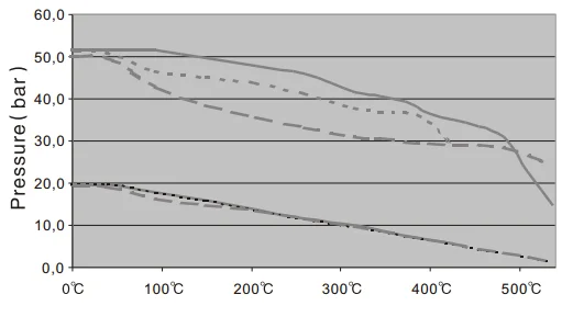
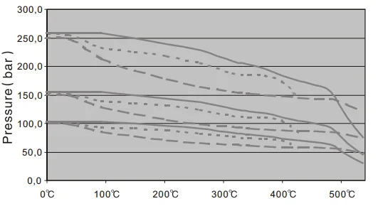
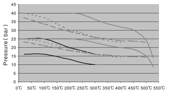
Figure 3 Temp.&Pressure curve | |||||||||||||||||||||||||||||||||||||||||||||||||||||||||||||||||||||||||||||||||||||||||||||||||||||||||||||||||||||||||||||||||||||||||||||||||||||||||||||||||||||||||||||||||||||||||||||||||||||||||||||||||||||||||||||||||||||||||||||||||||||||||||||||||||||||||||||||||||||||||||||||||||||||||||||||||||||||||||||||||||||||||||||||||||||||||||||||||||||||||||||||||||||||||||||||||||||||||||||||||||||||||||||||||||||||||||
Table 4 Rated Cv.
| |||||||||||||||||||||||||||||||||||||||||||||||||||||||||||||||||||||||||||||||||||||||||||||||||||||||||||||||||||||||||||||||||||||||||||||||||||||||||||||||||||||||||||||||||||||||||||||||||||||||||||||||||||||||||||||||||||||||||||||||||||||||||||||||||||||||||||||||||||||||||||||||||||||||||||||||||||||||||||||||||||||||||||||||||||||||||||||||||||||||||||||||||||||||||||||||||||||||||||||||||||||||||||||||||||||||||||
| | ||||||||||||||||||||||||||||||||||||||||||||||||||||||||||||||||||||||||||||||||||||||||||||||||||||||||||||||||||||||||||||||||||||||||||||||||||||||||||||||||||||||||||||||||||||||||||||||||||||||||||||||||||||||||||||||||||||||||||||||||||||||||||||||||||||||||||||||||||||||||||||||||||||||||||||||||||||||||||||||||||||||||||||||||||||||||||||||||||||||||||||||||||||||||||||||||||||||||||||||||||||||||||||||||||||||||||
Figure4 Flow characteristic curve | |||||||||||||||||||||||||||||||||||||||||||||||||||||||||||||||||||||||||||||||||||||||||||||||||||||||||||||||||||||||||||||||||||||||||||||||||||||||||||||||||||||||||||||||||||||||||||||||||||||||||||||||||||||||||||||||||||||||||||||||||||||||||||||||||||||||||||||||||||||||||||||||||||||||||||||||||||||||||||||||||||||||||||||||||||||||||||||||||||||||||||||||||||||||||||||||||||||||||||||||||||||||||||||||||||||||||||
Table 5.1 Allowable pressure differential ( Leakage classIV PTFE packing )
| |||||||||||||||||||||||||||||||||||||||||||||||||||||||||||||||||||||||||||||||||||||||||||||||||||||||||||||||||||||||||||||||||||||||||||||||||||||||||||||||||||||||||||||||||||||||||||||||||||||||||||||||||||||||||||||||||||||||||||||||||||||||||||||||||||||||||||||||||||||||||||||||||||||||||||||||||||||||||||||||||||||||||||||||||||||||||||||||||||||||||||||||||||||||||||||||||||||||||||||||||||||||||||||||||||||||||||
Continued Table 5.1
Note: 1 .”Ö” stands for bolt and nut impacted yoke ( Nor. Temp. ) , the rest is round nut impacted yoke ( Nor. Temp.or High Temp. ) . 2. The implication of “XX” is shown in SA series actuator specification. | |||||||||||||||||||||||||||||||||||||||||||||||||||||||||||||||||||||||||||||||||||||||||||||||||||||||||||||||||||||||||||||||||||||||||||||||||||||||||||||||||||||||||||||||||||||||||||||||||||||||||||||||||||||||||||||||||||||||||||||||||||||||||||||||||||||||||||||||||||||||||||||||||||||||||||||||||||||||||||||||||||||||||||||||||||||||||||||||||||||||||||||||||||||||||||||||||||||||||||||||||||||||||||||||||||||||||||
Table 5.2 Allowable pressure differential ( Leakage class IV PTFE packing )
| |||||||||||||||||||||||||||||||||||||||||||||||||||||||||||||||||||||||||||||||||||||||||||||||||||||||||||||||||||||||||||||||||||||||||||||||||||||||||||||||||||||||||||||||||||||||||||||||||||||||||||||||||||||||||||||||||||||||||||||||||||||||||||||||||||||||||||||||||||||||||||||||||||||||||||||||||||||||||||||||||||||||||||||||||||||||||||||||||||||||||||||||||||||||||||||||||||||||||||||||||||||||||||||||||||||||||||
Continued Table 5.2
Note: 1 .”Ö” stands for bolt and nut impacted yoke ( Nor. Temp. ) , the rest is round nut impacted yoke ( Nor. Temp.or High Temp. ) . 2. The implication of “XX” is shown in SA series actuator specification. | |||||||||||||||||||||||||||||||||||||||||||||||||||||||||||||||||||||||||||||||||||||||||||||||||||||||||||||||||||||||||||||||||||||||||||||||||||||||||||||||||||||||||||||||||||||||||||||||||||||||||||||||||||||||||||||||||||||||||||||||||||||||||||||||||||||||||||||||||||||||||||||||||||||||||||||||||||||||||||||||||||||||||||||||||||||||||||||||||||||||||||||||||||||||||||||||||||||||||||||||||||||||||||||||||||||||||||
Table 5.3 Allowable pressure differential ( Leakage classIV PTFE packing )
| |||||||||||||||||||||||||||||||||||||||||||||||||||||||||||||||||||||||||||||||||||||||||||||||||||||||||||||||||||||||||||||||||||||||||||||||||||||||||||||||||||||||||||||||||||||||||||||||||||||||||||||||||||||||||||||||||||||||||||||||||||||||||||||||||||||||||||||||||||||||||||||||||||||||||||||||||||||||||||||||||||||||||||||||||||||||||||||||||||||||||||||||||||||||||||||||||||||||||||||||||||||||||||||||||||||||||||
Continued Table 5.3
Note: 1 .”Ö” stands for bolt and nut impacted yoke ( Nor. Temp. ) , the rest is round nut impacted yoke ( Nor. Temp.or High Temp. ) . 2. The implication of “XX” is shown in SA series actuator specification. | |||||||||||||||||||||||||||||||||||||||||||||||||||||||||||||||||||||||||||||||||||||||||||||||||||||||||||||||||||||||||||||||||||||||||||||||||||||||||||||||||||||||||||||||||||||||||||||||||||||||||||||||||||||||||||||||||||||||||||||||||||||||||||||||||||||||||||||||||||||||||||||||||||||||||||||||||||||||||||||||||||||||||||||||||||||||||||||||||||||||||||||||||||||||||||||||||||||||||||||||||||||||||||||||||||||||||||
Table 5.4 Allowable pressure differential ( Leakage classIV Graphite packing )
| |||||||||||||||||||||||||||||||||||||||||||||||||||||||||||||||||||||||||||||||||||||||||||||||||||||||||||||||||||||||||||||||||||||||||||||||||||||||||||||||||||||||||||||||||||||||||||||||||||||||||||||||||||||||||||||||||||||||||||||||||||||||||||||||||||||||||||||||||||||||||||||||||||||||||||||||||||||||||||||||||||||||||||||||||||||||||||||||||||||||||||||||||||||||||||||||||||||||||||||||||||||||||||||||||||||||||||
Continued Table 5.4
Note: 1 .”Ö” stands for bolt and nut impacted yoke ( Nor. Temp. ) , the rest is round nut impacted yoke ( Nor. Temp.or High Temp. ) . 2. The implication of “XX” is shown in SA series actuator specification. | |||||||||||||||||||||||||||||||||||||||||||||||||||||||||||||||||||||||||||||||||||||||||||||||||||||||||||||||||||||||||||||||||||||||||||||||||||||||||||||||||||||||||||||||||||||||||||||||||||||||||||||||||||||||||||||||||||||||||||||||||||||||||||||||||||||||||||||||||||||||||||||||||||||||||||||||||||||||||||||||||||||||||||||||||||||||||||||||||||||||||||||||||||||||||||||||||||||||||||||||||||||||||||||||||||||||||||
| | ||||||||||||||||||||||||||||||||||||||||||||||||||||||||||||||||||||||||||||||||||||||||||||||||||||||||||||||||||||||||||||||||||||||||||||||||||||||||||||||||||||||||||||||||||||||||||||||||||||||||||||||||||||||||||||||||||||||||||||||||||||||||||||||||||||||||||||||||||||||||||||||||||||||||||||||||||||||||||||||||||||||||||||||||||||||||||||||||||||||||||||||||||||||||||||||||||||||||||||||||||||||||||||||||||||||||||
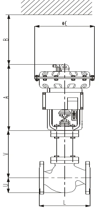
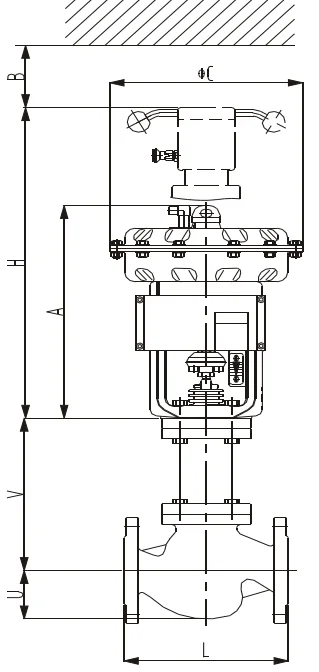
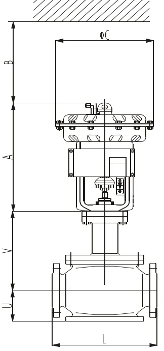
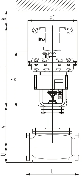
Figure 5.1 DN4015 ~ DN100 ( 1/2" ~ 4" ) | |||||||||||||||||||||||||||||||||||||||||||||||||||||||||||||||||||||||||||||||||||||||||||||||||||||||||||||||||||||||||||||||||||||||||||||||||||||||||||||||||||||||||||||||||||||||||||||||||||||||||||||||||||||||||||||||||||||||||||||||||||||||||||||||||||||||||||||||||||||||||||||||||||||||||||||||||||||||||||||||||||||||||||||||||||||||||||||||||||||||||||||||||||||||||||||||||||||||||||||||||||||||||||||||||||||||||||
| | ||||||||||||||||||||||||||||||||||||||||||||||||||||||||||||||||||||||||||||||||||||||||||||||||||||||||||||||||||||||||||||||||||||||||||||||||||||||||||||||||||||||||||||||||||||||||||||||||||||||||||||||||||||||||||||||||||||||||||||||||||||||||||||||||||||||||||||||||||||||||||||||||||||||||||||||||||||||||||||||||||||||||||||||||||||||||||||||||||||||||||||||||||||||||||||||||||||||||||||||||||||||||||||||||||||||||||
Figure 5.2 DN150 ~ DN400 ( 6" ~ 16" ) | |||||||||||||||||||||||||||||||||||||||||||||||||||||||||||||||||||||||||||||||||||||||||||||||||||||||||||||||||||||||||||||||||||||||||||||||||||||||||||||||||||||||||||||||||||||||||||||||||||||||||||||||||||||||||||||||||||||||||||||||||||||||||||||||||||||||||||||||||||||||||||||||||||||||||||||||||||||||||||||||||||||||||||||||||||||||||||||||||||||||||||||||||||||||||||||||||||||||||||||||||||||||||||||||||||||||||||
Table 6.1 Figure size (mm)&Weight (Kg) ( DN15 ~ DN100, DIN PN16/25/40)
Note: Weight=Body assembly+Actuator ( without handwheel ) | |||||||||||||||||||||||||||||||||||||||||||||||||||||||||||||||||||||||||||||||||||||||||||||||||||||||||||||||||||||||||||||||||||||||||||||||||||||||||||||||||||||||||||||||||||||||||||||||||||||||||||||||||||||||||||||||||||||||||||||||||||||||||||||||||||||||||||||||||||||||||||||||||||||||||||||||||||||||||||||||||||||||||||||||||||||||||||||||||||||||||||||||||||||||||||||||||||||||||||||||||||||||||||||||||||||||||||
Table 6.2 Figure size(mm)&Weight (Kg) ( 1/2" ~ 4" , ANSI150/300 )
Note: Weight=Body assembly+Actuator ( without handwhell ) | |||||||||||||||||||||||||||||||||||||||||||||||||||||||||||||||||||||||||||||||||||||||||||||||||||||||||||||||||||||||||||||||||||||||||||||||||||||||||||||||||||||||||||||||||||||||||||||||||||||||||||||||||||||||||||||||||||||||||||||||||||||||||||||||||||||||||||||||||||||||||||||||||||||||||||||||||||||||||||||||||||||||||||||||||||||||||||||||||||||||||||||||||||||||||||||||||||||||||||||||||||||||||||||||||||||||||||
Table 6.3 Figure size (mm)&Weight (Kg) ( DN150 ~ DN400, DIN PN16/25/40)
Note: Weight=Body assembly+Actuator ( without handwheel ) | |||||||||||||||||||||||||||||||||||||||||||||||||||||||||||||||||||||||||||||||||||||||||||||||||||||||||||||||||||||||||||||||||||||||||||||||||||||||||||||||||||||||||||||||||||||||||||||||||||||||||||||||||||||||||||||||||||||||||||||||||||||||||||||||||||||||||||||||||||||||||||||||||||||||||||||||||||||||||||||||||||||||||||||||||||||||||||||||||||||||||||||||||||||||||||||||||||||||||||||||||||||||||||||||||||||||||||
Table 6.4 Figure size(mm)&Weight (Kg) ( 6" ~ 16" , ANSI150/300 )
Note: Weight=Body asembly+Actuator ( without handwheel ) | |||||||||||||||||||||||||||||||||||||||||||||||||||||||||||||||||||||||||||||||||||||||||||||||||||||||||||||||||||||||||||||||||||||||||||||||||||||||||||||||||||||||||||||||||||||||||||||||||||||||||||||||||||||||||||||||||||||||||||||||||||||||||||||||||||||||||||||||||||||||||||||||||||||||||||||||||||||||||||||||||||||||||||||||||||||||||||||||||||||||||||||||||||||||||||||||||||||||||||||||||||||||||||||||||||||||||||
Ordering Information Please specify the following information: 1. Type 2. Nominal size 3. Nominal pressure & end connection 4. Body & trim material, harden treatment request 5. Flow characteristic 6. Packing material (code) 7. Actuator type, with handwheel or not & Air pressure supply 8. Action type (Direct or Reverse) 9. Accessory (with positioner & Air regulator or not) 10. Oil-free or Copper-free, etc. 11. Fluid Name & state (liquid, gas, steam, etc.) 12. Pipeline size, wall thickness (Inlet, outlet) 13. Nor. Flow, Max. flow & Min. flow 14. Flow pressure & Pressure differential 15. (Full open/close) 16. Flow temp., Gravity or Density 17. Inlet and outlet pressure 18. The Gravity & viscosity of fluid, with slurry, flashing or not 19. Used in high pressure, Temp., &EXP. Condition or not 20. Other special requests | |||||||||||||||||||||||||||||||||||||||||||||||||||||||||||||||||||||||||||||||||||||||||||||||||||||||||||||||||||||||||||||||||||||||||||||||||||||||||||||||||||||||||||||||||||||||||||||||||||||||||||||||||||||||||||||||||||||||||||||||||||||||||||||||||||||||||||||||||||||||||||||||||||||||||||||||||||||||||||||||||||||||||||||||||||||||||||||||||||||||||||||||||||||||||||||||||||||||||||||||||||||||||||||||||||||||||||
Lưu ý
Sản phẩm Van điều khiển SPL được phát triển liên tục, thông tin có thể có thay đổi mà không kịp thời thông báo đến Quý khách hàng!
Đánh giá sản phẩm của chúng tôi